This page describes the algorithm developed by Tenmoto
et al. [1] to construct a piecewise linear classifier. If you are not
sure what a classifier is, you should first read the classification
overview. This page consists of the following:
-
A preliminary discussion of concepts relevant to the algorithm
-
A description of the hyperplane construction process
-
A description of how hyperplanes can be used to define classification regions
in space
-
A general discussion of the algorithm
Preliminaries
Points and Prototypes
Before the algorithm can proceed, a set of prototypes must be generated
to represent the set of data points. Prototypes can be thought of as 'super
points', they are points that represent a group of actual data points.
Figure 6 shows five prototypes from three different classes, along with
the groups of data points they represent.
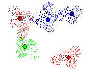
Figure 6 - Points and prototypes
A prototype represents a group of points of a single class in a region
of point space. One prototype represents more that one or more points,
but each point belongs to a single prototype. The location of a prototype
is determined by some measure of centrality of the set of points that it
represents, such as the center of mass. Prototypes can be generated through
clustering algorithms, such as the K-means
algorithm or minimal spanning trees, although the generation of prototypes
is not covered in the algorithm presented.
The Gabriel Graph
After a set of prototypes has been generated, their Gabriel graph
is constructed. In the Gabriel graph of a point set, edges exists between
all pairs of points such that the hypersphere who's diameter is the edge
between two points contains no other points. The Gabriel graph of a set
of prototypes is shown in figure 7.
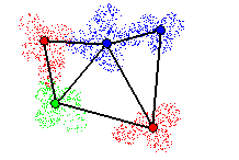
Figure 7 - Gabriel graph
Tomek Links
From the Gabriel graph, a subset of edges called Tomek links is
generated. A Tomek link is an edge in the Gabriel graph that connects two
prototypes of different classes. The set of Tomek links of set of prototypes
is shown in figure 8.
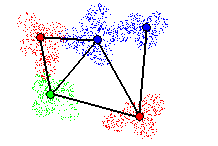
Figure 8 - Tomek links
Construction of Hyperplanes
Once prototypes and Tomek links have been generated for a set of points,
the algorithm to construct a minimal set of hyperplanes begins. To illustrate
the algorithm, a simple example is presented using the data set, prototypes
and Tomek links from figure 8.
The basic procedure is to find a set of hyperplanes that 'cut' Tomek
links, thus separating prototypes and points belonging to different classes.
Figure 9 shows a hyperplane (in purple) cutting a Tomek link. It is shown
later that a set of hyperplanes that cut all Tomek links divides the point
space into distinct regions, which can be used to classify points in a
piecewise linear fashion. The key concept is to cut as many Tomek links
as possible with each hyperplane, given the constraint that they must be
able to classify points with an error less that a predefined maximum acceptable
classification
error. This results in a smaller set of hyperplanes, reducing the complexity
of the classification according to a classification error limit.
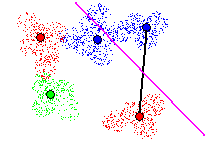

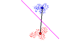
Figure 9 - Cutting a Tomek link. Local classification error rate of 0%
First, a hyperplane cutting a Tomek link is created and locally 'trained',
i.e. positioned such that its local classification error (i.e. classification
of points belonging to prototypes on either end of the Tomek link) is minimal.
Figure 9 how this is done via illustration, a more indepth description
can be seen here. If the hyperplane
is incapable of locally classifying points with an error rate less than
maximum acceptable error threshold, it becomes part of the set of hyperplanes,
and a new hyperplane is created on a new Tomek link. Once a Tomek link
has been 'cut' by a hyperplane, it is removed from the set of Tomek links
to be considered in the future.
If the hyperplane is capable of locally classifying points within the
maximum error threshold, it is then modified to cut other nearby Tomek
links. Tomek links are considered 'nearby' based on the distance of their
midpoints to the midpoints of Tomek links already cut by the hyperplane
under inspection. The distance to the nearest Tomek link is shown in figure
10 by the grey line connecting the midpoints of two Tomek links.
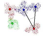
Figure 10 - Nearby Tomek links
As in the case with a hyperplane cutting a single Tomek link, the hyperplanes
cutting multiple Tomek links are locally trained to classify points on
either side with a minimal error rate. As long as the classification error
rate of the hyperplane is below the maximum acceptable error threshold,
the hyperplane is continually adjusted to cut new Tomek links. In figure
11, two nearby Tomek links are cut by a single hyperplane, which locally
classifies points with an error rate of 0%.
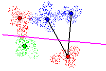

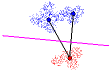
Figure 11 - Cutting 2 nearby Tomek links. Local classification error rate
of 0%
When cutting multiple Tomek links with a hyperplane, a new constraint is
added: all prototypes on one side of the hyperplane must belong to the
same class. This is called the class
limitation. This constraint states that hyperplanes are to define the
boundary between a particular class and any other classes. Figure 12 demonstrates
this constraint, where cutting the third Tomek link is acceptable since
all prototypes below the hyperplane belong to a single class.
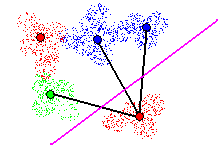

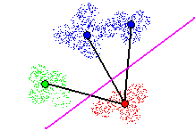
Figure 12 - Cutting 3 nearby Tomek links. All prototypes on one side of
hyperplane must belong to a single class
When no more nearby Tomek links can be cut by the hyperplane under inspection,
either because the classification error rate becomes unacceptable or because
of the class limitation, it is added to the set of classification hyperplanes,
and a new hyperplane is considered. Figure 13 shows a 2nd hyperplane added.
In this instance the location classification error rate is greater than
0% due to overlap of points from different classes, but it is lower than
the maximum acceptable error threshold.
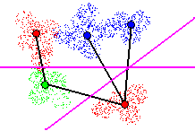

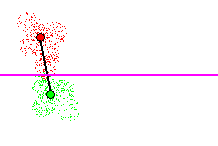
Figure 13 - Adding a 2nd hyperplane. Local classification error rate
> 0%, but acceptable
In figure 14, attempting to cut two links with the 2nd hyperplane results
in a local classification error greater than the maximum acceptable error
rate, due to point overlap of points from different classes. Cutting this
Tomek link is therefore not accepted.
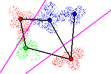

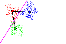
Figure 14 - Cutting 2 Tomek links with new hyperplane. Local classification
error rate > max acceptable error rate
Another attempt is made to cut a different nearby Tomek link in figure
15. The error rate is greater than 0%, but below the maximum acceptable
error rate, and therefore accepted. At this point, there are no other Tomek
links remaining to be cut by the hyperplane currently under inspection,
and the hyperplane is added to the set of classification hyperplanes.
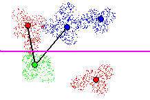

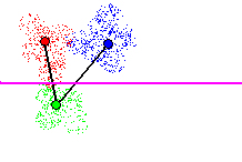
Figure 15 - Cutting 2 Tomek links with new hyperplane. Local classification
error rate > 0%, but acceptable
A 3rd hyperplane is then created to cut the last remaining Tomek link in
Figure 16. The classification error rate is greater than the maximum acceptable
threshold due to overlap of points from different classes, but the hyperplane
is added to the set of classification hyperplanes because there exists
no better hyperplane to cut the Tomek link. In total, three hyperplanes
are created for this example.
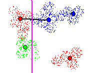

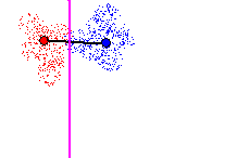
Figure 16 - Cutting Tomek link with 3rd hyperplane. Local classification
error rate > max acceptable error rate, but accepted
From Hyperplanes to Regions
Once the set of classification hyperplanes has been created, they can be
used to define regions in point space corresponding to unique classes,
which are used to classify points. Tenmoto et al. do not discuss how this
is done, but a simple demonstration is provided here to complete the algorithm
description.
For each prototype, there exits a subset of hyperplanes, which cut its
associated Tomek links. Each hyperplane in this subset divides the point
space into two distinct regions, one of which contains the prototype. The
union of all these regions containing the prototype defines a region in
point space, which isolates the prototype from all other prototypes to
which it is connected via Tomek links. In figure 17, the region formed
by this union is shown for the red prototype in the top left corner of
the example.
 U
U 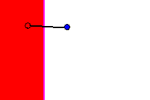 =
= 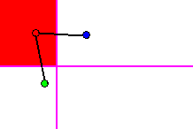
Figure 17 - Union of regions separating a prototype from all other prototypes
connected via Tomek links
The union of all regions isolating all prototypes of a particular class
from their Tomek neighbors defines a region (possibly disjoint) in point
space containing all prototypes the particular class, and no prototypes
of any other class. This union represents the entire subspace of the point
space in which points are classified as belonging to a particular class.
In figure 18, this region is shown for the red class from the example.
All points within the red regions are classified as being from the red
class.
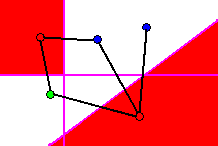
Figure 18 - Regions in which points are classified as being from the red
class.
The set of these regions for each class uniquely classifies all points
in point space. Figure 19 shows the final set of classification regions
for all three classes.
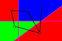
Figure 19 - Regions in point space uniquely classifying all points
Discussion
The algorithm presented for piecewise linear classification is useful in
that class boundaries can be constructed for a set of test data with a
desired classification error tolerance. The authors go so far as to present
a method for determining the maximum acceptable error via a minimum
description length calculation, although this was not discussed
in this report.
There are several subtle problems that reduce the algorithm's usefulness
however. Achieving classification under the maximum acceptable error threshold
is not guaranteed by the algorithm itself, since the first Tomek link cut
by a hyperplane in an iteration of the algorithm is guaranteed to be accepted
regardless of its classification error rate on associated data points.
This may or may not be a significant problem though, because if a hyperplane
cannot cut a single Tomek link with a classification error rate less than
the maximum error threshold, the error threshold is not achievable at any
rate.
Secondly, there is no guidance as to how many prototypes to use on a
particular set of test data. This is an important question - in the limits,
one could either use a single prototype for each class, or a prototype
corresponding to each data point. Either approach would have a very different
effect on the minimum error achievable and the generalizability of the
class boundaries.
This web page prepared by
Matt Toews (mtoews@cim.mcgill.ca)
as a term project for the course
Computer
Science 644 - Pattern Recognition
at the
McGill Center for
Intelligent Machines


![]()


![]()


![]()


![]()


![]()


![]()

 U
U  =
= 

