Lee 1983
Lee's algorithm [8] decomposes the plane into different regions which determine what actions should be taken. It's great contribution is that it is simpler to understand than the algorithm of McCallum and Avis, and that it uses only one stack. The algorithm of Graham and Yao is similar and was found independently around the same time as Lee's.
A few informal definitions are necessary, in order to present the algorithm:
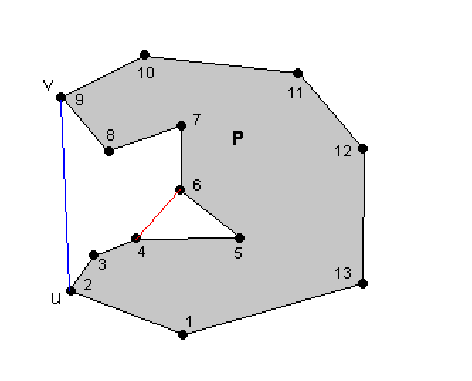
A lobe of a polygon P is a region exterior to P, which is bounded by P and one line segment L between two vertices of the convex hull of P.The line segment L is called a handle, and the remaining part of the lobe is called a body. Note that a lobe without a body is called a degenerate lobe.
In the figure below, the area between the blue segment and P is a lobe. The vertices of the lobe are 2,3,4,5,6,7,8,9. Note that in other references, similar concepts are described (lobes are sometimes called "pockets"). A difference, shown below, is that vertices 4,5,6 would form a "pocket" in many references, but in this algorithm they do not form a lobe.

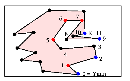
The version presented by Lee assumes that no three successive vertices are collinear. It is assumed that the interior of the polygon is to the left of the boundary (i.e. vertices are enumerated counterclockwise). After any iteration of the algorithm, the stack contains the convex hull of all vertices that have been examined, except vertices which are known to be in the body of a lobe. For example, in the figure below, all vertices up to K have been examined. The red vertices are on the convex hull of the vertices examined, but are in the body of a lobe, and therefore not on the stack. Vertices on the stack are shown in blue. Notice that vertex K is not on the convex hull of the vertices seen so far (and therefore not on the final convex hull) but it is currently on the stack since it is on the convex hull of the points seen so far if we neglect points that we know are inside lobes.. By the Jordan curve theorem K will eventually be discarded.

And now, the algorithm:
The first step is to locate the vertex with minimum y-coordinate, and push it on the stack. Then push the next vertex counterclockwise.
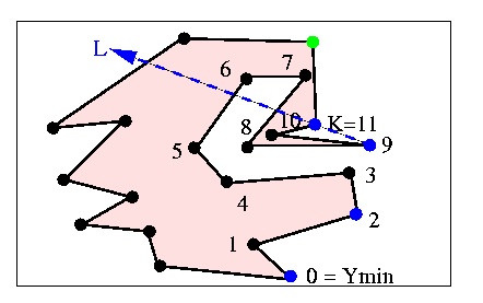
Now suppose that the stack contains a set of vertices, such as the blue points above. Call the next vertex to be examined the active vertex (shown in green below). Also define the directed line formed by the top two vertices on the stack as the current line, or L. These definitions are illustrated in the figure below.

A) If the active vertex is NOT to the left of L (as in the figure above)
Delete the top element of the stack. If only Ymin is left, push the active vertex and get the next one. Recompute L. Go back to (A).
B) If the active vertex is to the left of L
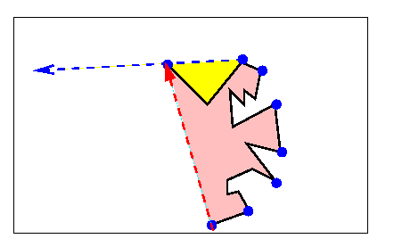
Case 1: active is in the lobe of the top two vertices of the stack (yellow region in figure below).Ignore the active vertex, make the next vertex active and go back to (A).Case 2: active is not in the lobe, but is inside the convex polygon of the stack (pink region).
Ignore the active vertex, make the next vertex active and go back to (A).Case 3: active is not in yellow or pink region (it's to the left of both dashed lines below).
Push the active vertex onto the stack, recompute L and go back to (A).

As you can see, if the active vertex is in the yellow or pink region, it can't be on the convex hull, so it is ignored. It's successors are also ignored until one emerges through the blue or red dashed line. At this point, any potential backtracking is done in (A), and then the active vertex is pushed onto the stack in (B). The process ends when Ymin is encountered again.
The time complexity of this algorithm is linear, for the same reasons mentioned in the 1972 Sklansky section.